![]()
![]()
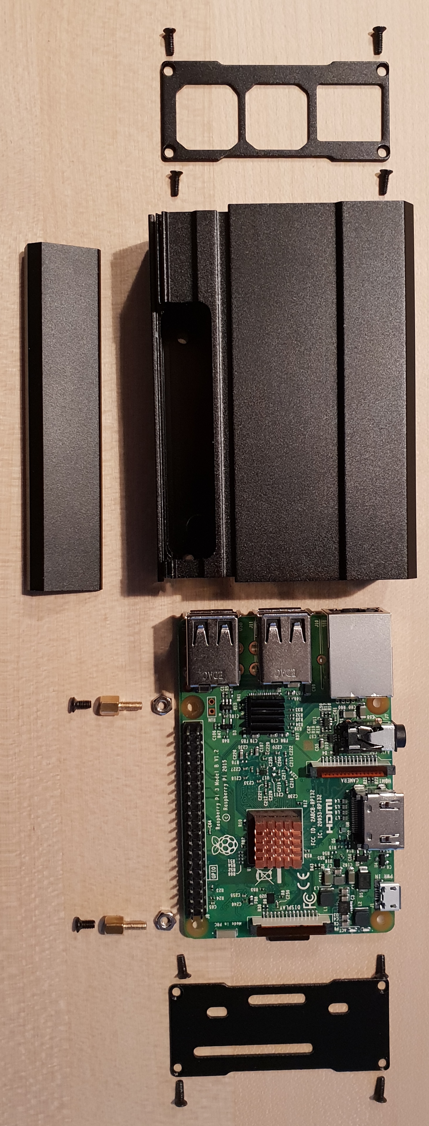 The assembly is done from top to bottom as shown in the adjacent figure:
The upper face is screwed to the housing with 4 cross-head screws. (Thick edge to the bottom of the housing)
The cover plate (shown left) is pushed into the housing from below.
The two hexagonal spacers are inserted into the board from the rear (solder side) next to each connector strip and fastened with the two nuts.
Glue the two heat sinks onto the matching chips.
Insert the board into the case so that the spacers are aligned with the holes in the case bottom. Make sure that the sockets of the board are fitted in the corresponding recesses of the housing.
Fasten the board to the bottom of the housing with the two cross-head screws.
Fasten the lower front face with the 4 cross-head screws.
(Fit the sockets.)
Copyright © 2020 HB9HCI Andreas Heertsch,